Factors of what you need to consider when selecting a micro magnetic gear pump
- Classification: ARTICLES
- Release time:2023-01-15 06:48
- Visits:292
Factors of what you need to consider when selecting a micro magnetic gear pump
- [Summary description] ARTICLES
- Release time:2023-01-15 06:48
- Visits:292
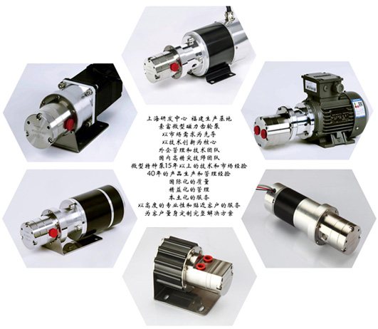
Micro pumps usually refer to pumps with small size and low flow rate. According to different technical principles, they can be divided into micro centrifugal pumps, micro gear pumps, micro diaphragm pumps, micro plunger pumps, micro peristaltic pumps, micro vane pumps, vortex pumps and so on. According to the driving method, they can be divided into direct drive and magnetic drive. According to the movement mode, they can be divided into reciprocating and rotary. According to the material, they can be divided into metal pump s, plastic pumps and composite pumps. According to the temperature of the liquid being transported, it can be divided into low temperature pump s , high temperature pump s and normal temperature pump s . According to different power sources , it can be divided into pneumatic pump s , DC pump s (12V , 24v , 48v etc.), servo pump s , AC pump s , frequency conversion pump s etc. However users often use their own actual usage requirements to name the pump such as circulation pump, pressure boosting pump, sampling pump, cooling pump, urea pump, chromatography pump, flushing pump, atomizing pump etc. With so many subdivisions it is inevitable that users will have a lot of confusion when choosing a pump . Here our company analyzes and makes some suggestions based on the structure and performance characteristics of micro pumps combined with common applications for reference when selecting a pump . No matter what type of pump all changes do not leave its origin their function is through work on the liquid being transported so that the liquid being transported produces a flow that meets requirements . Here comes out The most basic parameters for selecting a pump : flow rate and pressure . Generally speaking centrifugal pumps are difficult to achieve high lift (high pressure) at low flow rates so in situations where high pressure is required at low flow rates volumetric pumps appear frequently . One type is a micro gear pump .
The characteristics of a micro (magnetic) gear pump are:
(1) The active wheel and driven wheel need to mesh with each other during operation.
(2) The gap inside the pump is small with gaps between gears and body shafts and bearings in tens of microns range.
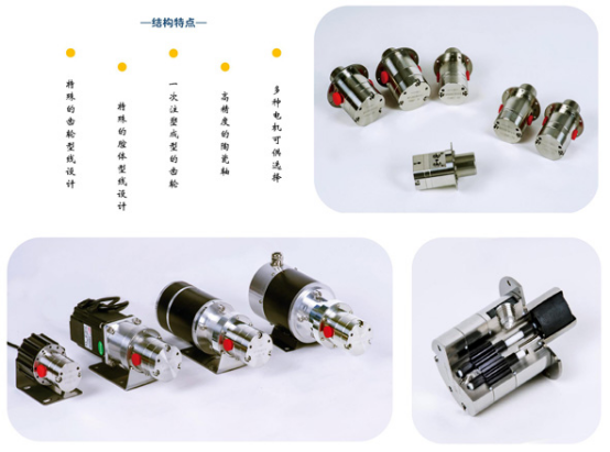
(3) Bearings and gears generally use polymer materials motor torque transmitted through magnetic couplings shaft.
So when choosing this type of pump you need to consider liquid flow rate inlet outlet pressure viscosity corrosiveness particle situation temperature sensitivity shear force inlet outlet pipeline situation motor type flow rate pressure control method (accuracy batch check valve) etc.”
1. Flow rate
Well-made micro magnetic gear pumps can generally operate within a speed range of 50~4000rpm. By looking up the flow-pressure-speed curve for each model, it is easy to select the right pump (lpm stands for liters per minute and the slash represents differential pressure).
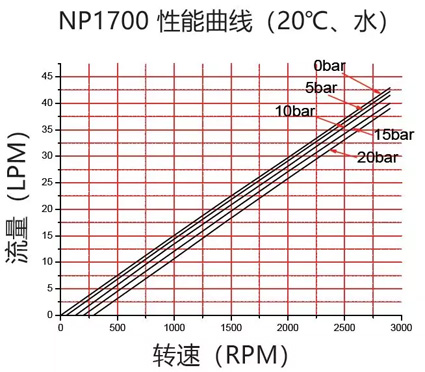
Due to the existence of gaps inside the pump, some high-pressure liquid at the pump outlet will flow back to the pump inlet along the internal gaps of the pump, resulting in an actual output flow rate that is lower than the theoretical value. And as the differential pressure between inlet and outlet increases, so does the internal backflow. The actual flow rate of a pump = its theoretical flow rate - internal leakage. From this graph we can see that at a constant speed, higher pressure results in lower actual flow rates. Additionally, when outlet pressure is stable, there is a linear relationship between pump flow rate and speed; this is why gear pumps can be used as metering pumps. However if pressure fluctuates then this linear relationship will be broken; this phenomenon is more pronounced in systems that transport low viscosity liquids.
2. Differential Pressure
Usually we only consider the differential pressure between inlet and outlet, but it is important to understand both inlet pressure and outlet pressure for correct selection. Because sometimes the inlet of the pump may be negative pressure or positive pressure. If it is a negative pressure situation, you need to know the specific negative pressure value. When the inlet pressure of the pump is less than atmospheric pressure, the flow rate of the pump at the same speed and differential pressure will be lower than normal value in performance curve. When inlet vacuum reaches an extreme value, pump will not work normally (NPSHa < NPSHr). In addition, each pump has a maximum allowable working pressure which is also known as maximum bearing capacity of pump. When inlet pressure > atmospheric pressure, outlet pressure must be < maximum bearing capacity of pump i.e., “inlet pressure + differential < maximum bearing capacity of pump” to ensure long-term safe operation of pump.
In addition, we also need to correctly understand outlet pressure of pump. Gear pumps are a type of volumetric pumps. We usually say that NP series micro magnetic pumps can reach 20bar differential which refers to ability of pump. However after installing a pump in a system its actual working pressure is determined by resistance in system. System resistance = liquid flow resistance in pipeline + possible container resistance.

In figure actual working pressure = liquid flow through pipeline pressure drop + liquid flow through valve pressure drop + tank internal resistance. If there are height differences causing additional resistance and bends causing additional resistance they should also be calculated.
3. Viscosity of Liquid
The viscosity of a liquid has an impact on both the performance and power of a pump, and is also affected by temperature and even shear force. Due to internal leakage in gear pumps, when pumping liquids with higher viscosity, internal leakage decreases and actual output flow increases. Therefore, compared to low-viscosity water, when pumping high-viscosity liquids at the same speed and differential pressure with the same model pump, the actual output flow will be larger (add comparison curve). However, as the viscosity of the liquid increases, its fluidity decreases. At the same time, the power required for gears to rotate in high-viscosity liquids also increases sharply. Therefore, as the viscosity of pumped liquid increases, pump operating speed should be appropriately reduced. This not only reduces unnecessary energy consumption but also prevents cavitation from occurring. When gear pumps operate, heat is generated due to meshing between gears and friction between bearings and shafts as well as losses from magnetic couplings. This can affect liquid viscosity. If liquid properties or process requirements are very sensitive to temperature changes then factors such as pump speed, internal clearance and tooth shape design should be considered during selection in order to limit pump work’s impact on liquid temperature. If a liquid is very sensitive to shear force then it should be addressed by reducing speed.
4. Corrosiveness of the liquid
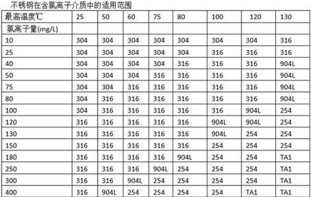
The corrosiveness of the liquid will seriously affect the service life of the pump. We must ensure that all parts of the pump that come into contact with the liquid can withstand the corrosion of the liquid being transported. Generally speaking, the 316L stainless steel material used in NP series gear pumps is relatively easy to find for its corrosion resistance to various liquids. Our ceramic shafts also have good corrosion resistance. The main thing is that PEEK/PPS gears and bearings need to be further considered for their suitability for different chemical media. PEEK and PPS themselves have good corrosion resistance and a wide range of applications, but some liquids will cause them to swell. Especially when they only have very slight swelling in some liquids, they may be judged as “usable” in other applications, but due to the very small internal clearance of micro-pumps themselves, these very slight swelling may cause pump death. Shanghai Suofu Industrial Co., Ltd. has a large amount of data to judge the compatibility between liquids and materials, but when certain materials are not in our existing database, we can also provide you with sample immersion tests. It should be noted that many times the corrosion resistance of materials is related to temperature.
5. Particle situation
Due to the tiny gaps inside the micro gear pump, any particles close to the gap range can jam the pump. Even very small hard particles can permanently damage the gears or bearings when they are running at high speed. Some particles exist in the liquid, and in many cases, the liquid may be clean, but there may be particles in system pipes and containers, joints and welds. This is especially common in newly installed or modified systems. Therefore it is recommended that users install a 300-400 mesh filter at the inlet of the pump for safety. In addition to ensuring that the material is not corroded by liquid when selecting a filter, it is also necessary to consider its temperature resistance, pressure resistance and flow area. If the flow area is too small it will cause excessive inlet resistance and may also cause frequent clogging of filters.
6. Temperature
1) Liquid Temperature
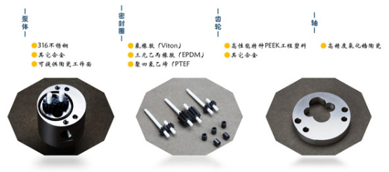
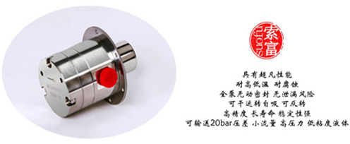
The pump components must be able to work stably for a long time within the liquid temperature range, including materials for pump body, bearings, gears, shafts, magnetic drives and seals. At the same time we also need to consider changes in maximum allowable working pressure at extreme temperatures. Especially for the thinnest part of pump body - magnetic shield’s pressure bearing capacity. For magnetic couplings we need to consider not only the heat resistance level of magnetic powder used but also aging temperature after magnetization. Shanghai Sofu Pump Industry’s NP series magnetic pumps have been aged at 150 degrees Celsius and can work stably in -40~150 degrees Celsius range for a long time. Liquid temperature will also affect internal clearance of pump. Because different parts have different materials and sizes so size changes under same temperature rise are different causing clearance changes. Generally speaking it may cause too small flow at low temperatures and pump may get stuck at high temperatures. So during initial consultation actual liquid temperature range under working conditions should be considered so that suitable internal clearance can be set when leaving factory. In other words even if our pumps can work between -40~150 degrees Celsius if liquid temperature provided during inquiry differs too much from actual range it is possible that pump will experience insufficient flow or get stuck during operation. Since pump and motor are connected with connecting frame heat from pump head will also transfer to motor which will have some impact on motor’s heat resistance level.
2) Ambient temperature
Ambient temperature has a great impact on the selection of motors. It may be necessary to configure low-temperature or high-temperature motors. If a brushless DC motor is configured, the impact of ambient temperature on driver performance is also quite large. In addition, some liquids will solidify at room temperature or low temperatures in winter. At this time, it is necessary to consider using pump head heating to ensure normal startup of the pump. A common method is to wind a heating belt around the pump head.”
7. The sensitivity of the liquid to shear force.
During the operation of a gear pump, the meshing between the driving wheel and the driven wheel will produce shear force. Some liquids are very sensitive to shear force. Under large shear force, the properties of the liquid will change until it can no longer be used. For these liquids, it is necessary to reduce the working speed of the pump and increase the internal clearance of the pump to minimize shear. More often, it may be necessary to choose pumps with smaller shear forces such as diaphragm pumps and peristaltic pumps to complete transportation. We can provide you with consulting services in this regard.
8. Inlet and outlet piping conditions
In general, the inlet and outlet pipe diameters should not be smaller than the diameter of the pump interface. To ensure normal suction of the pump, it is desirable to keep the inlet pipe diameter as short as possible and reduce elbows. All factors such as inlet pipe length or height difference between pump and liquid level can be attributed to the concept of NPSHa. The only difference is that NPSHa corresponds to a situation where the pump inlet is full of liquid. If the inlet pipeline is empty before the pump starts working, then it is necessary to consider the maximum allowable running time of the pump in a liquid-free state and its suction capacity in this situation. For self-priming situations, dry running capability and suction capacity during dry running are very important for pumps. Otherwise, pumps will burn out directly. Shanghai Sofu NP series micro magnetic gear pumps can achieve up to 100 hours of dry running time and about 1 meter vertical suction capacity in full dry state. Outlet pipe diameter will affect outlet system pressure, especially when transporting high viscosity liquids. Sometimes increasing outlet pipe diameter by one level can result in a 30% or higher reduction in pipeline pressure at outlet which can play a significant role in energy saving during daily operation. Gear pump outlet piping system should prevent back pressure. Our company provides DC brushless motors with overcurrent protection function and we also recommend users to install safety valves on outlet pipes where possible to prevent excessive outlet pressure from damaging pipes or pumps. Our products do not provide built-in safety valves for pump heads because these types of products are too small in size and once safety valves inside pump heads open all energy will drive liquid to circulate at high speed within narrow space inside pump head causing rapid rise in temperature of liquid.And also imported foreign micro gear pumps have experienced overheating caused by opening safety valve inside pump head resulting in stuck wear phenomenon (consult company for specific data).”
Dry operation: There are several typical situations for dry operation: 1.) Before the pump starts, the inlet pipe is empty and the pump needs to draw liquid from a distance into the pump. 2) After the delivery is completed and the system does not have an automatic shutdown function or there is a delay in the automatic shutdown function, the pump needs to run dry for a period of time. 3) The liquid being transported by the pump is very easy to vaporize or it is originally transporting gas-liquid two-phase media, and there is often gas in the pump.
Dry operation is a troublesome situation for liquid pumps because the structure and material design of the pump itself are designed for liquid transportation and do not consider too much about transporting gas during dry operation. For commonly used centrifugal pumps, users know that before starting the pump, they need to ensure that the inlet pipe of the pump is filled with liquid. However, when users hear that volumetric pumps have self-priming capabilities, they often think that they no longer need to consider inlet conditions. This can cause big problems.
The main problems come from
(1) excessive wear due to lack of liquid lubrication when gears mesh with each other;
(2) excessive wear due to lack of liquid lubrication when shafts and bearings move relative to each other;
(3) excessive wear due to lack of liquid lubrication when gear side faces move relative to each other. During this process, heat generated by excessive friction can cause material expansion and deformation or even direct jamming and damage of parts. At the same time, eddy current losses generated by magnetic couplings during operation can also cause heating of magnetic shields.
Shanghai Suofu Industrial Co., Ltd.'s NP series micro-magnetic gear pumps greatly alleviate these problems through special gear selection, bearing selection and shaft material selection as well as special gear profiles. Therefore all products in this series have good resistance to dry running ability. Among them NP039 model has undergone up to 100 hours of dry running test on test bench. The entire product line can fully cope with on-site dry running for several minutes.
9. The type and power selection of the motor
Generally speaking, motors can be divided into AC motors (ordinary AC motors, frequency conversion motors, explosion-proof motors, frequency conversion explosion-proof motors, single-phase motors, etc.), DC brushed motors, DC brushless motors (BLDC), stepper motors and servo motors. In the industrial field, various AC motors are used more frequently. First look at whether it is 1x220V or 3X220V or 3X380V. After determining the voltage, see if it needs to be explosion-proof (explosion-proof level) or frequency conversion. Choosing frequency conversion is usually because it needs to adapt to a certain range of flow rates. However, one is that the cost of a frequency conversion motor is high and a frequency converter must be installed. Therefore customers can also adjust the flow rate by bypassing the outlet. Since AC motor has a relatively large volume and low speed regulation accuracy it is inconvenient to install in many commercial equipment. At this time various DC motors stepper motor or servo motor can show their power. Ordinary brushed DC motor can directly adjust speed through power supply voltage but due to short brush life and small carbon powder after brush wear may cause harm to system so its use in various professional equipment is becoming less and less. Brushless DC motor has small size eliminates traditional brushes extends service life can manually adjust speed locally remote analog signal speed regulation or remote digital signal speed regulation and is increasingly accepted by market When customers need small flow rate and high control accuracy they can consider using stepper motor or servo motor Stepper motor has relatively low cost generally<800rpm so if you need large flow rate span and high precision it is recommended to consider using servo motor. Motor power = (flow * pressure / efficiency) * safety factor The difficulty in selecting motor power often lies in choosing safety margin For AC motor there are specified values for safety factors for different power motors in national standards But we still have to change safety factor reasonably according to actual use environment such as altitude, environmental temperature, environmental ventilation, continuous working time ,start-stop frequency ,speed regulation frequency ,overload possibility etc.
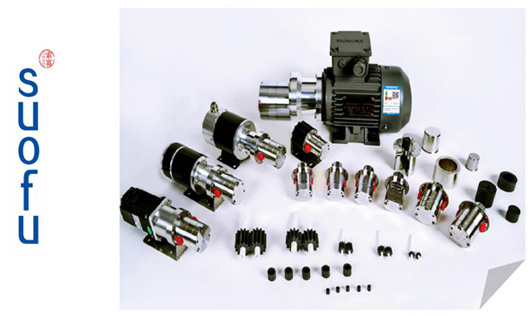
Shanghai Suofu Industry’s customized developed brushless DC motor power covers 40 watts to 1200 watts below 400 watts Motor can provide built-in driver option further reduce space occupation facilitate on-site installation We can provide local manual speed regulation or remote 0-5V voltage signal or PWM signal speed regulation support speed signal output function support positive and negative rotation control of motor Use environment temperature -40~80℃ protection level can reach IP66 We have also specially developed shielded built-in driver brushless DC for miniaturization applications Motor without rotor shaft for NP series products.
10. Flow and pressure control methods
The flow control of gear pumps is generally achieved by controlling the speed of the pump. For example, NP039 has a nominal displacement of 0.39 ml/rev, which means that for every revolution of the pump, it should theoretically output 0.39 ml of flow. So if the pump speed is 1000 rpm, then theoretically the pump should output a flow rate of 390 ml/min. Therefore, by adjusting the speed of the pump, it is easy to achieve the required flow rate. Therefore, when system requirements for flow accuracy are not high (about ±2%), using an AC variable frequency motor or DC brushless motor to control gear pump speed to achieve flow adjustment is a good way. In cases where higher accuracy is required (~0.5%), it is recommended to use a servo motor.
The accuracy of pump flow rate is also affected by fluctuations in outlet pipeline pressure. Many people may have doubts: isn’t pressure generated by pumps? How can it be affected by fluctuations in outlet pipeline pressure? Because the pressure behind a volumetric pump is actually determined by network resistance and load. If the outlet of a volumetric pump is directly connected to atmosphere, then its actual working pressure will be 0 (gauge). It’s typical “strong when encountering strong and weak when encountering weak”. Network resistance refers to resistance produced when liquid flows through pipelines; straight pipes, elbows, diameter changes and valves all cause pressure drops; loads can include height differences, container pressures and actuator power etc… Fluctuations in outlet pressure not only directly cause fluctuations in pump output flow rate but also cause torque fluctuations due to pressure fluctuations which in turn cause motor speed fluctuations. Therefore in precise metering systems it’s necessary to install a regulator valve after the pump and use motors with low torque variation influence on speed.
Gear pumps have different structures from piston pumps and diaphragm pumps; both have inlet/outlet check valves inside so liquid cannot flow when stopped. Gear pumps do not have built-in check valves so liquid can still flow inside pipelines when stopped causing “dripping” or air entering pipelines after stopping for some time. If these phenomena are undesirable then install a check valve with as low an opening pressure as possible at the outlet. Additionally gear pumps without internal check valves also have many advantages such as being able to simply reverse motor direction before stopping to drain liquid inside pipelines back into inlet tanks without experiencing “air lock” phenomena like diaphragm pumps.

-
-
- 客服联系方式
服务时间:9:00 — 18:00
24小时售后
Contact
-
Mr Lin:TEL(wechat):+86 13764319509
mail:lqx@s-fluid.com
whatsapp:966578718101
R & D sales: Room 602, 18 Feet Building, No. 597, Langao Road, Putuo District, Shanghai Production base: Building 10, Sanming Zhongguancun Science Park, No. 9, Yingbin Avenue, Qiujiang street


